Archive for the ‘electrical’ Category

Charge!: Chargers, Plugs, and Receptacles On Boats

Clark March 27th, 2017
IMG_2365
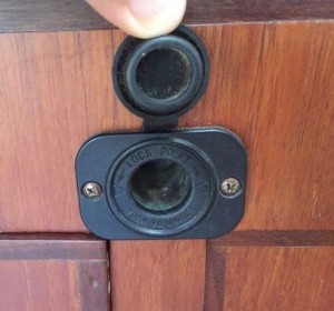
The cigarette lighter plug/receptacle has long been the de facto standard to connect portable 12-Volt devices, and it sucks. Nobody smokes anymore. It’s bulky, insecure, makes poor electrical contact, and can’t carry high current. It’s got to be the only electrical connector in the history of electrical connectors with a compression spring that is constantly trying to break the connection.

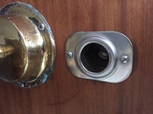
I suffered many a night when the only difference between a good sleep and waking up in a pool of sweat, ravaged by mosquitoes, was a 12-Volt fan plugged into a cigarette receptacle above my bunk. If I so much as twitched, it disconnected. If the boat rocked it disconnected. It spontaneously disconnected, because the little spring was always trying to push the plug out of the receptacle. And this was with a stainless steel receptacle from West Marine and a Marinco plug, both purveyors of quality marine equipment.

The receptacle above my bunk looks all marine and stainless steely, but it wants to spit out plugs:
IMG_2363

We’re stuck in this backward compatible nightmare simply because cars started coming with cigarette lighters way back when. There has to be a better way. Some enterprising company has to invent the better mousetrap, sell it to the world, and commit to it for twenty years or so, long enough for the world, or as least us boaters, to banish the cigarette lighter receptacle forever. Blue Sea Systems? Marinco? Cole-Hersee? I’m calling you out!

Currently there’s just not much out there to adopt, even if we all agreed to lop off all those cigarette lighter plugs and make a collective switch. There are lots of good in-line connectors (connectors that connect two pairs of wires together), but we don’t want some pigtail hanging out of our nav station: We want a streamlined, sexy little receptacle.

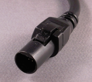
The closest thing I’ve found is the EmPower plug/receptacle, used on some airlines. It’s 15-Volt DC (close enough to 12) but limited to 75 Watts, and 75 Watts at 12 Volts is only 6 Amps, and that’s not much. I’m guessing the connector itself could take much more, but the in-flight systems limit it to 75 Watts so you can’t actually charge your laptop, which is apparently a fire hazard at altitude. Anyway, the EmPower plug/receptacle is barking up the right tree:
Empower_jack

Some features this future dream receptacle and plug should have:

1. Compact: It can have a way smaller footprint than a cigarette lighter receptacle and the plug shouldn’t stick out nearly as far.

2. Polarized: Can’t be any way to plug it in backward and reverse the polarity.

3. Rated for 20-30 Amps: Should be able to plug in a 450-Watt portable inverter and have it work.

4. Secure: Yes, but don’t need to go overboard. I think a home 110 AC plug/receptacle is about right in this regard: You can vacuum the whole room and shake the cord every which way and the plug won’t pull out of the wall, but if you accidentally roll the vacuum cleaner down the stairs the plug will pull out. I don’t think there needs to be a locking mechanism, per se, as with a shore power cord, but if you’re using a plug-in spotlight in full combat mode, it shouldn’t come loose when you move about the cockpit (another personal pet peeve).

5. Circuit protection?: I say no. Many cigarette adapters have a fuse in the plug, but this isn’t the place for circuit protection. There’s not a circuit breaker in the plug for your toaster. The circuit supplying the receptacle should be protected by an appropriately-sized fuse or breaker, then any further protection should be in the device itself.

6. Easy install/adaptation, especially for the plugs: Installing the receptacles can take however long it takes, but installing the plug on a new device should be quick and easy. This way, if some of us are are to adopt this new dream connector and ditch our cigarette receptacles, and we buy some new device that comes with a cigarette plug, it should be a joy, rather than a chore, to lop it off and replace it with one of our dream plugs.

Anything else?

Back to reality and what we’re stuck with. Marinco and Blue Sea Systems make the only cigarette receptacles/plugs worth their salt. They’ve taken lemons, and made lemonade, so to speak. I have several of them aboard, and they really are better. The receptacles themselves are superior, in and of themselves, but used with their plugs it’s the best deal going. The plug twists and locks – sort of – into the receptacle, and at least holds the spring in compression and prevents unintended disconnects. Not cheap at about $30 for a receptacle/plug combo, and another $15-$20 for additional plugs:
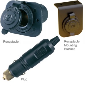
343576

It’s worth having at least one of these receptacles, then the corresponding plugs for your mission critical devices. For me these are the portable inverter, the spotlight, the fan, and a 12-Volt vacuum cleaner.

USB connectors are now ubiquitous for charging all kinds of devices, and powering a few, but USB operates at 5 Volts, so forget about powering 12-Volt devices. Still, it makes sense to install one of the marinized USB receptacles for phones, iPads, and the like. Without one you’re looking at additional adapters and claptrap, or running an inverter, just to charge a phone:
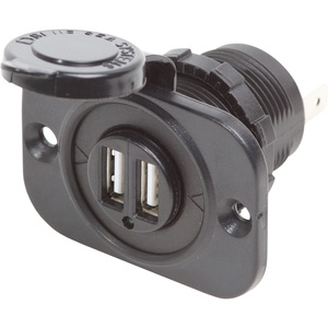
16016032_FUL

Or one of these combination panels, with the cigarette receptacle and the USB ports:
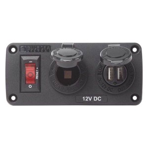
17054198_LRG

They sell combination AC outlet/USB sockets, so if you’re running AC all the time this is kind of nifty. I installed one at home, and it cleans up our charging station somewhat. We just need the cords now, without the adapters:
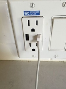
IMG_2149

Advanced Electrical: Diodes

Clark February 7th, 2017

FB9UV6OH5JVXMX1.MEDIUM
The most common diodes on boats these days are LEDs, Light Emitting Diodes, which are changing the way we light our boats and use energy. They’re great! There are all kinds of specialty diodes in the electronics world, but the kind of diodes I’ll discuss here are basic, simple old diodes, the kind you could buy at Radio Shack for thirty-five cents, if Radio Shack were still in business. I always keep a few diodes in my box, because they provide a magic solution to some very specific problems.

Diodes are one-way valves for electricity. Place a diode along a wire and electricity will flow one way down the wire, but not the other. If you connect an LED the wrong way it won’t light up; connect it the proper way and voila. Above is the electrical symbol for a diode, and as you might guess, the arrow points in the direction of current flow. Current can’t flow against the arrow.

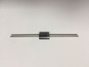
It’s good to know the symbol, and basic symbols for switches, fuses, and the like, because when considering a diode to solve a problem, diagramming the circuit first really simplifies the matter. An actual diode looks like this, and the silver band is the cathode end, that is, the end the current flows out of, but not into:
IMG_2646

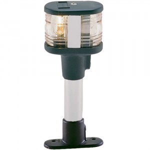
There are several common situations when I use a diode on a boat. The first is when I’m installing a light like this:
123497
It’s got a bulb in front, and one in back. When you want it to be an all-around light, or anchor light, you power both; when you want it to just be a steaming light you only power the front bulb. Sounds simple, but it’s not so simple. Since the the two bulbs share a negative wire (three wires, not four, lead into the assembly) you’ll quickly find it’s hard to separate them: Both bulbs will light together when you only want the steaming light.

The simplest way to avoid this is by using a DPDT switch (Double Pole Double Throw), a switch with ON-OFF-ON settings and various terminals for isolating the various loads. Turning this switch to one of the ON positions gives you your all-around light; turning it on in the other gives you your steaming light, maybe along with the nav and stern lights. But sometimes this setup isn’t practical, and many electrical panels come with one switch for an anchor light and one switch for a steaming light. Enter the diode.

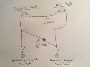
By placing a single diode in this circuit you can make your two switches do what you want them to do:
IMG_2649

If you follow the circuit you can see that without the diode, unintended current would flow from our steaming light circuit to our anchor light circuit and make the aft bulb light up too. If, in the same circuit, we had nav and stern lights connected to our steaming light switch, then they’d light up when we turned on our anchor light. A second diode would prevent anchor light current from flowing to our nav and stern lights.

Another common use for diodes is for engine alarms. The standard setup is to have a light/buzzer that goes off when you’ve got high water temperature or a drop in oil pressure. Well, which is it? It would be nice to know at a glance whether the alarm is from high temperature or low oil pressure, and to have a separate light for each. Depending on the way the panel is wired, you’ll sometimes get the same problem as with our pole light, both bulbs lighting when you only want one, and a diode can isolate them.

Electricity can be sneaky, especially on engine panels and distribution panels where you’ve got a lot going on in the same place. Sometimes, even in a well-designed and well-built panel you’ll get a sneaky phantom current that makes bulbs glow dimly or buzzers/beepers make irritating noises. Again, simple placement of a diode can solve the problem without completely dissecting your handiwork.

Also found on boats are solar panel blocking diodes: Solar panels “leak” a bit of juice at night, so the blocking diodes prevent this back flow. Solar blocking diodes (indeed all diodes) add some resistance to the circuit, reducing the panel’s output somewhat, so the day/night balance ends up being about a wash.

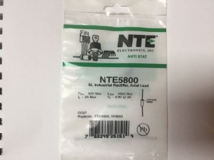
Basic diodes usually have four different ratings, most of which can be ignored for our purposes. I always use NTE5800 diodes, which are rated for up to 3 Amps of current. I know I’m never going to have more than 3 Amps, because I’m always solving problems like those above, with small bulbs, buzzers and the like, in 12 or 24-Volt DC systems.
IMG_2650

The NTE5800 diode takes .9 Volts to “turn on,” that is, to function, and I’m always going to have that in a 12 or 24-Volt system. It’s rated at 200 Amps to break it, that is, the amount of reverse current to make it fail and not block. 200 Amps ain’t gonna happen either. It also has other ratings for the amount of abuse it can take in either direction before it fails, but these aren’t ever going to happen in my applications. I just need to remember it’s good for 3 Amps, and if I ever try to do something exotic I might need a different diode.

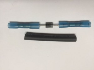
In practice I like to install diodes using two heat shrink butt connectors to connect the diode’s two leads to wires. The leads on the diode are live and exposed, so I always then cover the whole thing with heat shrink tubing, both protecting from accidental shorts and waterproofing it (I think they’re waterproof anyway). Then definitely label it on the outside with some kind of label (white heat shrink tubing works well), otherwise it will just look like a mystery blob inside some heat shrink tubing. It’s also very easy to bend the terminals on the diode, insert them into two of the terminals on a screw-down terminal block, then connect your wires to the opposite terminals.
IMG_2647

Electrical Fire! (and some lessons learned about starters)

Clark January 2nd, 2017

IMG_2541 (1)

Voice Mail: “Hi Clark, it’s (name withheld). I was out sailing today with my daughter and we had an electrical fire on the new starter you installed. Because of the fire we lost the engine and hit the south tower on the Golden Gate Bridge, called the Coast Guard, and had to be towed back to our berth. When I opened the engine compartment there were six inch flames rising from the starter, but I was able to blow them out. I don’t know where that leaves us, but I’d sure like to speak with you.”

Not what a marine electrician wants to hear. After my initial panic, I reflected that this was a basic R&R (remove and replace) of an old starter for a new one. I’d tested it several times, by cranking and starting the engine, and all seemed well. Various scenarios flew through my mind – defective starter, defective solenoid, some sort of shorted wire, stuck solenoid or stuck starter button, or, eh gads, installer error. I called the owner, who was very understanding, and was back on his boat the next day. If you look at the photo above, all the insulation on all the wires leading to the starter is fried, and was burning until he blew it out.

After an initial check, I called the owner and told him that no matter whose fault it was, the damage was probably less than the deductible on his insurance, and that I might as well remove the starter and start the replacement process. He agreed. I pulled the starter and found it well-burnt, and the solenoid completely melted, with both of the studs loose. The main linkage between the solenoid and the starter motor had acted as a fuse, melted through, and ended the fireworks:
IMG_2543

I took it back to the starter store, where they were very understanding and agreed to replace it under warranty, but also opined that something had probably got stuck, and that the starter probably wasn’t at fault. They noted some damage to the pinion gear, which I hadn’t noticed.

I installed the (second) new starter and continued my postmortem, finding very quickly that the cranking circuit was closed, as in, if I’d connected it the starter would have started cranking and wouldn’t have stopped. In this instance the boat had a starter button, separate from the key switch that energized the circuit, and the button was stuck:
IMG_2562

Blessed sweet mother of God, it wasn’t my fault! I replaced the button, and the burnt wires, tested it all out, and all was well, for the second time. The owner was very understanding, ended up buying my wife and me a nice bottle of wine, and we decided we owed the guys at the starter store a case of beer.

There are some interesting things that happen with a stuck starter, one of which I didn’t know about. I knew about shorts, of course, and 98% of high amperage starter circuits aren’t protected with fuses, so these can be spectacular. And I knew about all kinds of unintended open circuits, as with bad motors, bad solenoids, etc. But I always thought that a stuck starter, as in, a starter that stays engaged after the engine starts, would just burn out its innards or strip its pinion gear.

Nay. A starter that stays engaged after an engine starts gets spun continually, much faster than its intended rotation speed, and actually becomes a generator, sending high current back into the electrical system. In most cases the batteries and cabling can handle the current, but the starter can’t. It gets very hot and finally burns up (from high current, rather than friction, overheated brushes, or whatever). Even in normal use a starter is an intermittent duty motor: With a recalcitrant engine you should only crank it for ten seconds or so at a time, then give it thirty seconds to cool off, and to allow the surface voltage to come back on the battery.

So, it is very important to make sure your starter disengages after your engine starts. In most cases this is obvious, as in your car, where if you held the key in the cranking position, or the starter got stuck this way, you’d hear it. But on many boats it’s not so obvious, since the engine panel might be some distance from the engine, and once started the engine noise can drown everything else out.

This boat happened to be a Catalina, and on Catalinas it’s standard to have a starter indicator light on the instrument panel. This is a good feature, and not common on other boats, but you’ve got to know it’s there:
IMG_2563

On this boat it was there and still worked, but the owner didn’t know about it, plus it’s hard to see in daylight, and easy to miss in full combat mode (they were close to the south tower of the Golden Gate Bridge in an outgoing tide, after all). But also on Catalinas, and many other sailboats, the engine panel is exposed to the elements in the cockpit, sometimes gets kicked a lot, and generally takes a beating. In this case the starter button saw constant rain and spray, and eventually corroded and got stuck.

On my boat I’m standing right over the engine when I start it, so I’d hear it in a nanosecond if my starter got stuck, but not so on many boats. If it wouldn’t be obvious to you if your starter got stuck, you should consider an indicator light or buzzer. When you consider that it would result in not only a destroyed starter, but in not being able to start your engine again, and maybe an electrical fire, it’s worth some thought.

Shore Power Cord Economics

Clark December 13th, 2016


Unfortunately, as in the photo above, the connectors on shore power cords often get toasty. It always seems to happen on the neutral connector (white wire in the US system) and I don’t know why. Maybe the electrons get all gummed up and dirty from being on your filthy boat, then get stuck on the way off?

Sometimes it happens on the male side too, and the guts of the shore power inlet have to be replaced:

At any rate, a burned/melted shore power cord is bad, and should be repaired, but therein lies the rub. The new connector for the end runs about $35, but that’s not all. In order to make it like before you also need a new boot, which you can buy with or without the threaded ring, but call it another $15:

So now we’re up to $50 (prices vary, but you get the idea) in parts alone to repair a shore power cord. Fifty foot, 30 Amp shore power cords sell for as little as $80, if you shop around. It’s fairly straightforward to re-terminate a shore power cord, which a do-it-yourselfer can easily do. It takes me about ten minutes, but it’s easy to see that the cost of parts, plus the cost of a marine electrician quickly makes the cost about a wash.

To do it right you’ll want some good wire strippers, a cable stripper (judicious use of a box cutter will suffice), a cutter big enough to lop off the whole fried end cleanly, then it’s nice to have a multimeter or AC tester to check that you haven’t reversed something that will really make things burn. So the task becomes daunting without all the proper tools, and if you don’t have the right tools they’re not cheap.

So what are we to do? It’s terrible that we live in such a throw-away society. I once toured the second largest open pit copper mine in the world, in southern Peru, and it’s no small feat to get copper out of the ground and turn it into copper wire:

So alas, if you just need to replace one end of a 50-foot, 30 Amp cord, repair costs enough less than replacement that you should fight the good fight and do it, if you can do it yourself or your electrician happens to be around working on other things anyway. If you have to replace both ends it’s cheaper to just buy a new one. If the whole cord is looking fairly tired and sun-baked, then definitely replace the whole thing.

If it’s shorter than 50 feet, it’s probably not worth repairing it.

For 50-Amp cords the whole magilla gets much more expensive for either repair or replacement, but the economics are about the same.

Copper wire should always be recycled, but finding where to do this can be a pain. As a marine electrician I take a big box to be recycled every year. Back during the height of the economic crisis people were desperate and copper prices were at an all time high, so shore power theft was common.

Advanced Electrical: Galvanic Isolator Case Study

Clark November 4th, 2016


Once I was buying a galvanic isolator in a West Marine store, when a West Marine employee, of all people, was really insistent that I shouldn’t buy it: “Those things are a scam! They don’t do anything. I have it on good authority that they’re a big waste of money!” He had that look in his eye, so rather than get all marine electrician on his ass, I just said, “Well, my customer wants it, so I think I’ll buy it all the same.” There are a lot of misconceptions about the purpose of a galvanic isolator, and what it can and can’t do.

Flash forward to this week when another friend/customer calls me down to his boat, says his zinc anodes are being eaten too quickly and he’s thinking about a galvanic isolator. When I get there he shows me a propeller shaft anode that a diver had replaced just over a week before, and it’s already over a third eaten. To get to that stage should take a few months.

A galvanic isolator will sometimes, but by no means always, solve the anode-eating problem. A galvanic isolator is installed in-line along the safety ground (grounding conductor, green wire) in the shore power connection, so of course if you’re not plugged into shore power at a dock, then you’re barking up the wrong tree.

My customer was plugged into shore power, but being a thorough guy I unplugged him from shore power and did a galvanic survey of all the underwater metal items on his boat using a reference cell, dangling in the water, connected to a digital multi-meter. All the numbers came up about right for a standard fiberglass boat, his bonding system was all intact, and he had the right amount of zinc anodes to protect his underwater metals.

But if we plugged in his shore power cord, his hull potential changed by about 200 millivolts. Aha, problem found, but people want to point to some AC problem, since this is coming from the AC shore power cord. Nay. Galvanic corrosion and stray current corrosion are caused by DC currents.

In fact, I could measure half an Amp of DC current by putting my Amp clamp, on the DC setting, around his shore power cord.

If your boat is bonded properly then all of the major metal parts, above and below water, are bonded together, usually using big green wire. It will also have an AC safety ground, also usually green wire, connecting all the AC outlets and appliances, just like at home. These two systems cross-connect at one, and only one, point. So, when you plug into shore power, your boat is connected, via the safety ground, to the safety ground system on every other boat on the dock, and thus to the bonding system and all the underwater metals, on every other boat on the dock. What could possibly go wrong?

My customer may have been doing everything right, but since his bonding system is connected to his AC safety ground system, and since his neighbors’ boats are the same, and since they’re all connected together via the AC safety ground wires in their shore power cords, his zinc anode was protecting his boat plus the boat next door, or maybe down the way, or maybe all the boats down the row. But even though it’s via the AC shore power cord, it’s galvanic corrosion, which means a DC current.

It could also be stray current current corrosion, that is, corrosion caused by an electrical current, but stray current is still a DC thing. AC current just doesn’t cause or accelerate corrosion in normal circumstances.

Whether his half an Amp of DC current came from pure galvanic action or stray current corrosion is beyond my pay grade. I tend to think the latter, because half an Amp is quite a bit. Maybe there’s no way to tell, but the solution, in any case, is a galvanic isolator.

A galvanic isolator blocks low level DC currents from traveling down the AC safety ground.

It doesn’t do anything about galvanic corrosion within the confines of the boat it’s on, thus the corrosion survey before zeroing in on the galvanic isolator. As a marine electrician, I think I had to go this route to rule out other causes beforehand. If I just slapped a galvanic isolator on there without poking around, I’d have to advise him to have his diver come back in another two weeks to check the anodes, and this would cost more than my additional poking around.

Before the galvanic isolator was installed:

And after:
IMG_2431

Voila! But two days before I’d read .5 Amps, instead of .3 Amps. What changed? I don’t know, but .3 is still bad.

As a boat owner who is constantly/often plugged into shore power, should you just slap one on as a matter of course?: Yes

Will it solve your problem with fast anode depletion?: Probably maybe.

But even if you don’t have a problem now, you may in the future, as your fate is tied to all those other boats on the dock, so it’s good insurance. It’s especially good insurance when you compare the couple hundred bucks for the galvanic isolator to the financial ruin of a devoured prop and shaft, keel/keel bolts, outdrives, et al. It’s not just about saving anodes; it’s about saving what gets eaten after the anode is gone.

Likewise, it will not solve a stray current problem within your boat. If you’ve got nasty old exposed bilge pump wires sitting in the bilge water, you might just stray current your keel off.

And a galvanic islolator only protects against low level DC, up to 1.2 or 1.4 Volts, so if there’s some banzai stray current issue in your marina, which creates a voltage higher than that, the isolator won’t do anything, but this would be unusual.

It used to be that a galvanic isolator could fail, not only negating its anti-corrosion purpose, but creating a potentially deadly break in the AC safety ground. So after that they made it so you had to have a monitoring system that would warn you if its function was compromised. Now, galvanic isolators are fail safe, meaning that if they lose their anti-corrosion function they still maintain their AC safety ground function. They are still supposed to be tested annually. If you’ve got an older galvanic isolator, you should replace it with a fail safe.

There is a magic box called an isolation transformer that makes all of this go away, but isolation transformers are big, expensive, and heavy, so not practical for the average sailboat…unless your sailboat is steel or aluminum, in which case you should pony up and make the space.

Teaching Marine Electrical Seminar In Sausalito This Saturday

Clark October 25th, 2016

How many wrong things can you find in this picture?

If you happen to be in the Bay Area this Saturday, October 29th, I’m giving a marine electrical seminar at Spaulding Marine Center in Sausalito, where I will teach electrical excellence, simplicity, and how not to get electrocuted. They suggest a $50 donation and always provide a great lunch. Starts at 10:00AM; goes to about 2:30. Please RSVP. Link here for registration

Electrical Basics: Bus Bars

Clark October 17th, 2016

IMG 2377

Just twenty or thirty years ago the electrical system on the average sailboat was very simple. It had two batteries connected to an OFF-1-2-BOTH battery switch, and all the loads were fed from there:
IMG 2313
On the back of the battery switch were three studs: one for each battery, and one for the common, that is, the terminal that connects to the alternator and all the loads:

IMG 2314

The battery switch for this Catalina 30 is this way. In addition to the connection to each battery, the battery studs on the back of the switch are good places to connect the outputs for the shore power charger, the voltmeter, and the bilge pump, all things we want permanently connected to a battery, and never turned off.

On the common terminal of course is the big cable connected to the engine’s starter, and the feed wire to the main distribution panel, which in this case is just a 10 gauge wire: ah, the days of such simplicity. The back of this switch might be a little crowded, but all of these wires fit.

Today the electrical system on the average sailboat is more robust and complex. With just the aforementioned connections to the battery terminals – voltmeter, charger, bilge pump, maybe the memory wires from a stereo or other electronics – the studs are already too crowded. On the common terminal, forget it. You might have the big cable to the starter, a big cable to an inverter or inverter/charger, big cable to the windlass, and a good-sized cable to feed the main distribution panel, which now supplies a radar, a refrigerator, and a range of modern comforts.

All these cables simply won’t fit, and according to the ABYC standard, you shouldn’t stack more than four ring terminals on a stud anyway.

Enter the bus bar. Give yourself some breathing room!

A bus bar simply expands your single stud into four or more. A large gauge cable, and nothing else, connects to the common stud on the battery switch. The other end connects to the bus bar, where you’ve got a row of big studs for all the other connections. The same could be done for one of the battery connections if you find you’ve got too many cables and wires that need to be connected directly to a battery, without a switch in between. Generally speaking, we want to keep our battery terminals clean. Manufacturers sometimes dictate otherwise, as with some electrical system monitors and chargers, but we should endeavor to have nothing but the supply cables connected to our batteries.
IMG 2369

The bus bar is even more necessary on the negative side, where the negative cables from the batteries, negative ground from the engine, inverter, windlass, corrosion ground (green wire), and feed to main distribution panel, all must connect. Might also note here that bus bar covers are equally important, as they make for a lot of exposed, live metal:
IMG 2367

Many older boats foresaw this scenario, but it was before off-the-shelf bus bars, so they just added distribution studs, or what Blue Sea Systems now calls a Power Post, but one stud just isn’t enough. These are overcrowded and a bus bar would create more room, make circuits easier to trace, and ahem, that thing about no more than four ring terminals to a stud?:
IMG 2231

Now Blue Sea Systems has gone plum crazy with the PowerBar 1000. It’s the Super Jumbo Extra SuperMax GT version of the bus bar. I have yet to find use for one, but when I do I’ll know I’m serious:
IMG 2342IMG 2343

Remember, good wiring is not only electrically sound, but easy to follow. Wherever you find yourself running out of room and trying to cram too many terminals in a tight space, even if it’s electrically sound, it will be difficult to service and trace in the future. A relatively cheap and simple bus bar is often the solution.

Tesla’s Powerwall on a boat?

Clark September 17th, 2015

Tesla
This summer Tesla unveiled its Powerwall, a battery large enough to power an average home with a solar system, and give this home independence from the grid. Elon Musk’s announcement was met with giddy excitement, and the batteries are already sold out for the foreseeable future.

I wonder how long before a Powerwall finds its way onto a boat? Tick, tick, tick.

Crunching the numbers, it may not make economic sense yet, but the price may come down in a few years. The Powerwall, the 7 kWh version, sells for $3000. The slightly larger 10 kWh Powerpack sells for $3500. If we compare these to a size 8D battery (generally the largest size, and common on boats), here’s how it stacks up.

8D battery:

An 8D holds about 3 kWh (kilowatt hours). You can buy an 8D battery for as little as $230, but for our purposes we’ll compare a top quality AGM 8D battery, say from Lifeline or Trojan, which sells for $650-$700. So in pure kilowatt hour terms, the Tesla battery costs about 40% more. You’d need three 8D batteries (a common arrangement, and what I’ve got on my boat) at about $2100 to supply to same number of kilowatt hours as the Tesla Powerpack at $3500.

But wait! With the lead-acid batteries we normally follow the 50% rule, meaning we only use 50% of the battery’s capacity. Tesla doesn’t expressly say this, but since the Powerwall/Powerpack is a lithium-ion battery I’m guessing it can cycle through it’s entire capacity without damage. This alone might make up for the difference in price. Also, lithium-ion batteries can take a charge must faster than lead-acid batteries. The Tesla also comes with a 10-year warranty, and I don’t know of too many marine batteries that see ten years.

The Tesla is WAY cheaper than other quality lithium-ion batteries of similar capacities.

The voltage on the Tesla batteries is stated as 350-450 Volts DC (huh?) so there would have to be some kind of DC to DC step-down converter. I can’t find much information on these, and they don’t seem to be common, but we can assume this will get expensive…and be one more device aboard that can fail.

Another advantage of the Tesla is that it’s lighter at 220 pounds. A single 8D weighs about 160 pounds, so the Tesla would be about half the weight for the same capacity. The Tesla is a big, flat battery at 51″H x 34″W x 7″ deep, so it might lend itself well to fitting under a bunk or mounting in the back of a locker. It’s meant to mount on a wall (duh) and it’s all sexy-looking, so maybe it could just mount in plain sight on a bulkhead.

It’s a deep cycle battery, so I have no idea how it would do for starting loads. Might have to have a starting battery too, which would provide some redundancy.

At the moment I’m going to say it’s a bit premature, especially with regard to stepping down the voltage, but the Tesla batteries are a VERY interesting prospect for powering a boat.

Boat Wiring: Distribution Panels and Circuit Protection

Clark July 9th, 2015


The wiring phase of this project started with re-terminating cables and adding big fuses, then moved into battery switches and distribution. Now we’re into the final leg, which is the main distribution panel.

In the photo above you’ll see what I went with. Most distribution panels in the marine world use breakers, like this:

That’s what I thought I was going to end up with, and the exact one above would have been just peachy, but I ended up going with glass fuses in fuse blocks for a few reasons. First, they’re way cheaper. Second, I’ve already got so many things aboard that take glass fuses that I’m pretty much stuck with them anyway. I’ve got this blast-from-the-past sub-panel with nine circuits, original equipment from England in 1967, which still works great:

I built this new instrument panel, which has glass fuse holders for all the switches, which is often the done thing with instrument panels. And the bilge monitor console, on the left side? Glass fuse:

In fact, all bilge pump consoles seem to have glass fuse holders:

And there are lots of other glass fuses hidden here and there throughout my boat – in the autopilot, in the HF radio – so I figured if I was going to be carrying a bunch of glass fuses anyway, I might as well go big and continue to use them on my main distribution panel. Also, the breaker-as-switch function on breaker panels is often unnecessary, and is in fact unnecessary on all the circuits on my distribution panel. If you’re going to turn on, say, your spreader lights, then the breaker-switch on the panel makes perfect sense: It’s providing your switch and your circuit protection all in one. But if you want to turn on a cabin light the “Forward Cabin Lights” or “Starboard Lights” switch on the panel doesn’t need to be there as a switch; it just needs to provide circuit protection. IE I don’t want to have to flip two switches when I can just switch one to turn on the bloody light.

Ergo, the glass fuse panels: When the batteries are turned on, everything served from the panel is energized, just the way I want it. If I need to do maintenance on a circuit I can just pull the fuse.

Finding quality fuse blocks proved a challenge and I ended up with my old friend the Blue Sea Systems 5015 and 5018, which I’ve recommended as an electronics sub-panel before in this article for SAIL:

The 5015 has a negative bus and the 5018 doesn’t, so I used two 5015’s and one 5018 because some of my circuits just needed in-line fuses, like the ignition feed to my regulator. I like these products because they are tinned, and seem to be the only tinned glass fuse blocks in the industry. Rather than buy an untinned fuse block with the right number of holders, I daisy-chained two of these together to give me 12 circuits with positive and negative. This whole arrangement was less than $100, where a breaker-switch panel would have been around $500. It goes without saying that I will build a beautiful teak cabinet to house this arrangement, and on the front of this cabinet will be my new Victron battery monitor and other gauges and switches, but for now it’s functional and inside the main cabin, which was the whole point of this exercise: