Archive for the ‘marine electrical’ Category

The Future Is Here: Bottom Cleaning Nanobots

Clark April 1st, 2016

150127124327-nanobots-mc1-super-169
With copper-based antifouling paints just being banned in Washington state, the writing is on the wall. We’re going to have to figure out an an environmentally-friendly way to keep the critters from growing on the bottoms of our boats. That’s where BottomBot comes in.

Dan Stein, BottomBot’s CEO says, “We took our technology from the medical industry, where nanobots have long been in development. There is a family of nanobots designed to be released in the blood stream to remove plaque from the insides of your arteries. These nanobots aren’t quite ready for prime time in medicine, for safety reasons, but the bottom of a boat is much less sensitive than say, your aorta.”
nanobots-red-graff

BottomBot’s first product in in beta testing on 25 boats in the Pacific Northwest. Sam Stanton, a beta tester, says, “It’s like having a bunch of little pets. I can’t see them of course, but sometimes at night I think I can hear them. It’s not perfect yet – some parts of my bottom stay cleaner than others – but my boat hasn’t had any antifoul on in for eight months, and these are quite fertile waters, and the nanobots seem to remove all the growth.”

The base product for a 40-foot sail or power boat includes 2000 nanobots and a charging station. The charging station looks like a scoop for a thru-hull, and each nanobot must make its way back to the charging station once a day, where its tiny battery gets magnetically recharged.

contemporary-stair-and-step-lights
“Our biggest hurdle was getting them to stick to the bottom.” says Stein “It was fine while the boat was sitting the the berth, but once a boat hit 8 knots a lot of the bots washed off, and this got expensive. We experimented with a ferrous bottom coating, so the bots could attach magnetically, but this just exchanged one metal-based bottom coating for another, and introduced corrosion issues. We ended up with a patented design where the nanobot is shaped like a limpet, and moving water actually helps it stick to the bottom at high speed. Still, a few get lost, and some fail, every week, so every year or two you’ll need to replace a couple hundred bots to retain good cleaning ability on your entire hull.”

Each bot has simple directional programming that sends it out over the bottom in random direction. “It works kind of like a bunch of Roombas,” says Stein, “Then each bot has a tiny scraper, and just removes anything softer than epoxy as it moves along.”

Initial pricing is expected to be over $15,000 for a 40-foot boat, but the prices are expected to come down. “When you consider that this gets you out of doing bottom jobs forever, it eventually pays for itself,” said one of the beta testers.

“The boat’s bottom ends up free of marine growth, but eventually there is this accumulation of grey goo.”

Save Your Boat!: Remote Boat Monitoring and Killer Apps

Clark January 7th, 2016

IMG_1816
For Christmas our house got the Nest thermostat and smoke alarm/carbon monoxide detector, smart devices that connect to a smartphone app via Wi-Fi. Such devices are part of the Internet of Things, in which the electronic things in our lives communicate with us and control themselves by learning our patterns and schedules.

Upon installing the Nest smoke alarm/carbon monoxide detector, I thought hey, I could put one if these things on my boat, and as long as it’s in Wi-Fi range it would send me a warning if my boat caught fire. At $100, with a free, slick app, this could be pretty cheap insurance. Then I wondered if there might be a way for it to also send a warning if my boat was taking on water, but there was no easy way to do this. It dawned on me that being a marine electrician I could easily rig a high water float switch to trigger a small electrical fire, which would then activate the smoke alarm and let me know my boat was sinking. I knew I was onto my next multi-million dollar idea, so I popped into one of the venture capital firms down in Menlo Park. They said, “Clark, you had us at electrical fire,” but a quick competitive analysis revealed that greater minds have been on the case for years: There are several remote boat monitoring platforms.

When I think about what I’d like to know about my boat when I’m away, it boils down to these three things:
1. Is it sinking?
2. Is it on fire?
3. Is it going somewhere without my knowledge? (IE Has it been stolen, have the dock lines parted, is it dragging anchor, or has its mooring parted?)

But apparently I’m thinking small. These systems can send all manner of information to your smartphone, from your battery charge level, to fluid levels, to ambient temperature, or even if someone has undone one of the snaps on your boat cover. You can control various pumps, lights, and switches remotely, or even have a look around the main cabin via remote camera. Still, I maintain that the Nest smoke alarm/carbon monoxide detector is a cheap and cheerful remote fire alarm for a boats that have Wi-Fi at the dock or at their marina.

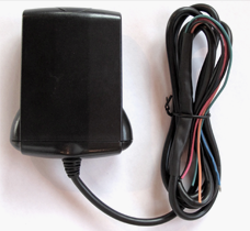
These systems all use proprietary electronic base stations, which reside on your boat somewhere, and this base station connects to the various sensors. Most systems come with the basic sensors (high water or bilge pump activity, high temperatur/fire, GPS location and “geofencing”), or terminals to connect to existing devices (like a bilge pump), and then have open slots for additional sensors and controls. Prices are reasonable, at $300 to $800 for the hardware with no frills.

The platform of choice seems to be cellular, which is touted as the most reliable, but of course will only work while your boat is in cellular range, and not far offshore. Cellular monitoring costs $9-$15 per month.

The GOST system, based in Ft. Lauderdale, is satellite-based (Inmarsat) with worldwide tracking. GOST seems to be more focused on the megayacht market, and I assume it’s more expensive, but they also sell basic tracking devices.

Of the cellular-based systems, Siren Marine and Boat Command are based in the US. Siren Marine offers a seasonal subscription, which brings the price down for snowbirds.

One of Siren Marine’s base stations:
pixie_shot

Boat Warden is based in Ireland, C-Pod in Sweden, and Boat Guard in the UK.

The C-Pod base station:
C-pod

I think these systems will become as commonplace as security systems on cars. At less than a thousand dollars for a sophisticated hardware platform that monitors all manner of things aboard, and under $200 per year in subscription fees (and I’m rounding the prices up) it’s a relatively small price to pay for peace of mind, security, and convenience.

Yes, some spectacular boating disasters have come from relying too much on electronic gadgets, and I’m sure blind trust in these systems will cause some spectacular disasters too, but sinking, fire, and theft are among the top causes of boat loss, and one of these systems could reduce the instances of all three substantially.

Several of the systems offer a “buddy alert” feature, so people other than the owner can get the alerts too. If one of those people were the marina manager or boat neighbor, it would up the chances of getting someone on the scene quickly. If insurance companies get onboard with discounts for boaters who have such systems (who will have a lower risk of loss from sinking, fire, or theft) these systems might pay for themselves.

New Steering Wheel Adventure: Part 3

Clark August 3rd, 2015


After many deviations, diversions, and delays, the steering wheel project is finally finished (see part 1 and part 2). What started as buying a new steering wheel on Ebay turned into rebuilding the entire teak console, re-wiring much of the boat, servicing and adjusting much of the steering system (installation of the new wheel changed the geometry of things just a tad), building a new instrument panel, and all new senders on the engine to go with the new instruments.

I’ve blogged about instruments, senders, and instrument panels before (see Gauge of Confusion), but now we’ll go in a little deeper.

The fist thing to keep in mind is that the instrument panels from the engine manufacturers are often a rip off. You can build your own using better components for much less. More importantly, it will be exactly the way you want it. People are figuring this out, and aftermarket panels for various engines are all over the Internet.

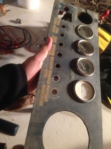
I built mine with idiot lights, analogue gauges, a bilge monitor console, and seven fused switches to control other stuff for about $275, but I kept a few of my old instruments. In my case it’s a very customized shape and size for my boat, and I wanted to cram a lot of stuff into the this small piece of real estate:

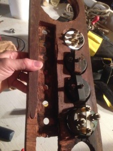
The next thing to keep in mind is the material of the panel: Never, under any circumstances, try to make it out of anything thicker than 1/4-inch. Switches, gauges, lights, etc. are all built for thin panels, and if you have something thicker you’ll be in for a lot of frustration. See my old panel for examples of futile and unnecessary adventures with a chisel…and see how trashed my old panel was. I just couldn’t put it back looking like that:
IMG_1514
IMG_1513

I have lately built all my instrument panels out of black, 1/4-inch Starboard. It’s easy to cut and drill, I think it looks good, and it’s got a matte texture that hides dirt and fingerprints.

As to engine instruments and senders, they’re just as confusing as they’ve always been. I’ve learned all about these things, and I still ran into trouble. Check out this email from VDO, a quality international gauge manufacturer who I’d bought three new gauges from. I’d spent hours on their website and just could not find what I needed:

Good Morning Mr. Beek,

Thank you for your inquiry.

This instrument is designed to work with the OEM sender that’s also a 220F Temp gauge. VDO does not manufacture a corresponding 220F temp sender. If you require a replacement, parts that may work can be found at;

Standard Ignition: TS-6 1/2′-14 thread
KEM Manufacturing” TW-3 12′-14 thread and TW-106 M114X1.25 thread
Autozone(Duralast): TU201, 3/8′-18 thread

Please let us know if we can further assist you.

VDO Sales Team

Kudos to them for at least telling me who I could buy the right bit from. As I said in Gauge of Confusion, the right sender for the gauge must cover the same range as the gauge, vary its resistance in the right range for the gauge, and be the right size to fit an existing hole in your engine. Drilling a new hole would take a leap of faith and risks a mistake that you’d be too embarrassed to share with others.

Looking at the right side of my instrument panel, we’ve got my good old mechanical tachometer, which has worked for nearly 50 years, so why change it? Next to that we’ve got the engine gauges for water temperature and oil pressure. Below those two gauges is the idiot light/buzzer for water temp and oil pressure. If that alarm goes off, I quickly check the gauges to see whether it’s high water temperature or a drop in oil pressure that has caused the alarm. I think it’s important to have both the idiot lights and the gauges: the gauges for precise readings and data over time; the idiot lights to actually alert you, unless you happen to be looking at the gauge when something goes wrong.

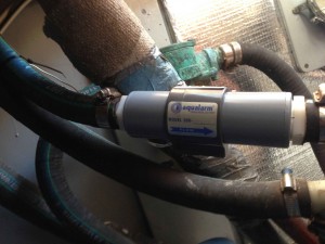
Under the tachometer is a second idiot light/buzzer. This one is for the new Aqualarm raw water flow sensor I installed:
IMG_1630

After many years of fretting about my engine, it occurred to me that this flow sensor, attached to an alarm, could be key. You could have a complete raw water flow failure (failed pump, broken hose, blocked intake) and it would take several minutes for your engine to heat up enough to trigger the water temp idiot light. In the mean time you’re frying an impeller, melting your exhaust hose, and maybe damaging the engine itself. I wired it to a second idiot light/buzzer because it was a bit complicated and fiddly to have three different devices connected to the same light/buzzer and keep them straight. My flow sensor is just before the exhaust injection elbow, so it would tell me if anything had gone wrong in the entire raw water circuit.

Along the bottom of my panel are seven switches and fuses, which aren’t labled yet, but they are: Bilge blower, instrument lights, compass light, spare, windshield washer (yes, call me crazy, but when the salt gets caked on this will be a Godsend), port wiper, and starboard wiper.


On the left side of my panel I’ve got an Aqualarm Bilge Monitor, which I really like. Next to that is the old engine hour meter, which has the recorded hours on it, so I wasn’t about to change it. And next to that is the transmission pressure gauge, which always says the same thing no matter what, but I guess it would tell me if I lost my transmission fluid.

The big red thing at the lower left is a switch that silences the alarms, but the red thing would have to be sticking up like a sore thumb with the alarms turned off, so I won’t be able to forget. This way, when I’m starting the engine in the early morn I don’t have to wake everyone up with the alarms, as they will go off for 10-15 seconds until the flow switch gets triggered and the oil pressure comes up.

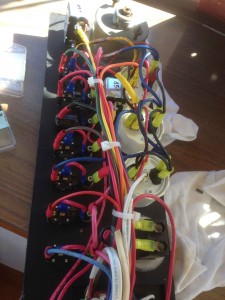
As to the wiring on the back of the panel, it looks like a rat’s nest, but it’s pretty simple:
IMG_1523

Each gauge has three connections on the back, labeled +, GND, and Sender. The GND just goes to ship’s negative. The + should connect to the accessory tab on your ignition key, along with the regulator. Sender connects directly to the appropriate sender on your engine. Since your engine is grounded (negative in most cases) the sender makes or breaks, or varies the resistance of, this second negative connection to the gauge.

Each gauge also has a light, which needs positive and negative, so now we’ve got five wires connected to the back of each gauge. Many things on the backs of instrument panels can be daisy-chained together: Ship’s negative can hop from one negative connection on the back of a gauge, then the negative connection to the light on the gauge, and on to the next gauge. Same with positive from the key switch, which can go to all the gauges, and to the positive sides of the idiot lights. It’s okay to crimp up to three wires into the same ring or slip-on terminal.

You need circuit protection for your panel, so a fuse in line with the key switch is simple.

My bilge monitor is largely separate from the other stuff on the panel, and my row of seven switches has a separate feed and it’s own fuse.

The only problem with all this brand new teak and varnish is it makes the rest of the boat look like crap:

Boat Wiring: Battery Switches and Distribution

Clark June 5th, 2015


Above is what the main cabin ends up looking like when you’re in the middle of a project like this.

In my last installment I covered battery cabling and big circuit protection. Now we’re to the next stops down the line: the battery switches and core distribution.

First, the battery switches. I blogged once before that I like basic battery switches. These big, basic switches from Cole-Hersee have been around for at least sixty years, maybe longer:

My boat already had two that were original equipment and still fine, but the threads were stripped on part of one of the posts and they’d seen a lot of dousings and abuse, so I replaced them, and added a third for the starting battery. Part of this project is to move all the key electrical stuff out of a cockpit compartment, where it might be subject to flooding, and put it in the main cabin. Here are the new switches, right above the trash can, now in the main cabin:

I’ll add some labels at some point, but for now I know the one on the left is Battery 1, the middle is battery 2, and the one on the right is the starting battery. Turn the switch one way and that battery is connected to the main bus for supplying power or to be charged. Switch it the other way and it’s disconnected.

A 1-2-Both-Off switch or a Blue Sea Systems Dual Circuit Plus battery switch doesn’t allow me to do those simple things:

These battery switches are great for switching two battery banks, and combining them, but not three. In practice my Bank 1 and Bank 2 will usually be combined and treated as a single bank, but not always, so I’ve got them on separate switches. The way I’ve got it now I have to remember to connect the starting battery to the main bus to charge it, and disconnect it after I kill the engine so I don’t run it dead. At some point I might add an Automatic Charging Relay or Balmar Digital Duo Charge, but for now things are cheap and simple.

Now to the other side of the bulkhead, in the engine room:

You’ll see the three switches, with the big cables from each battery coming up from below and connecting to the lower post on each switch. Along the top I’ve used a piece of copper bar to connect the three switches, forming a main bus. Using copper bar allows these switches to be spaced tightly together. Trying to connect them as is with cable would be impossible, and connecting each to a separate bus with cable would create a rat’s next.

To substitute copper bar for cable, figure out the cross-sectional area of the cable size you’re trying to emulate, then get copper bar of the same or greater cross section. In my case I wanted the same current carrying capacity as 1/0 cable, which has a cross sectional area of about 54 square millimeters, or 3/32 of an inch. 3/4″ x 1/8″ copper bar has the same cross section, and is the right size and shape to suite my purpose, but I overkilled it slightly and ordered two feet of 3/16″ x 3/4″ copper bar from www.onlinemetals.com. There’s nothing more exciting than two feet of copper bar arriving in the mail.

To the left of the three switches you’ll see a Blue Sea System’s Power Post Plus, which is connected directly, with a large cable, to the battery side of the battery 1 switch. This is because there are a few things that need to be connected directly to a battery, whether the battery switch is on or off: bilge pumps, and the memory circuit for the stereo. You want the bilge pumps connected directly to the battery so they’re always live. If you don’t have your stereo memory connected, you lose your preset radio stations every time you shut the boat down.

In the photo I haven’t connected any of these things to the Power Post yet, but I will. What I do have connected are the two outputs from the alternator. I thought a dual output alternator was a good idea back in the day: It isn’t. Just get a single output alternator. We have better ways to charge multiple banks now. Anyway, I connect the alternator outputs directly to the battery side of the switches so there’s no risk of somebody switching off the batteries with the engine running and blowing the alternator diodes. (If alternators don’t have somewhere to send their charge, bad things happen.)

I added the Power Post Plus because all these things are too much to stack onto the post of the battery switch: You’ve got the cable to the battery, the alternator outputs, the bilge pump, and the stereo. That’s already too many to fit, and exceeding ABYC standard (you’re only allowed to cram four on a terminal). Plus I know there will be a connection to a battery monitor, at some point, and other things I haven’t thought of, so I just needed more real estate for direct connections to battery 1.

All of these battery connections and copper bar adds up to a lot of exposed, live metal, so I’ll be making a cover out of Starboard that will protect all this from dumb guys in the engine room.

To pan out, we can now see the whole magilla, on the bulkhead forward of my engine:

Mind you this is mid-project and all those wires will get tidied up. In the upper right hand corner are the battery switches. At the lower left and right are the positive and negative main buses, with a few red and black cables connected. In the case of the positive bus, it’s an extension of the bus I made with the copper bar, giving me more big, 5/16-inch posts to connect stuff to.

In the middle is a Blue Sea Systems Safety Hub:

I’m not a shill for Blue Sea Systems: They just seem to be the only manufacturer who makes quality electrical components for small boats. The Safety Hub is meant to be a main distribution panel/fuse block for a much smaller boat, but for me it served as the most compact way to to get four AMI fuse blocks, and some additional negative bus terminals, in a small space. It also has six ATO/automotive fuse slots at the bottom, which I won’t use.

AMI or MIDI fuses seem to be the best way to protect circuits from 30 to 200 amps (glass fuses only go up to 30 Amps), and I have four such circuits I needed to protect. My boat has sort of a convoluted early version of a distributed power system, with four distribution panels spread about the boat, so each of these bigger circuits serves these four distribution points.

In the next installment we’ll cover those…

Boat Wiring: Reterminating Cables and Adding Big Fuses

Clark May 28th, 2015


This is the project that started with a new steering wheel, but I’ve drifted to far from the new steering wheel that I’ve almost forgotten that that’s how I started. There is a running theme to this project run amok and it goes like this: After disassembling things to get done what I needed to get done, the disassembled components were in such sad shape that I couldn’t, in good conscience, put them back. This started with peeling wood veneer, which necessitated rebuilding the entire steering console, and now I’m into the wiring. It’s a bit of a cobblers children without shoes scenario: Here I am a marine electrician, but much of my boat’s wiring was a mess. This is attributable to several factors:

1. I’m still finding original wiring, as in, installed in England in 1967, and I thought I’d routed all of it out by now.
2. I’m still finding wiring done by former owners of the boat, like with lamp cord, and I thought I’d routed all of that out too.
3. I redid a lot of wiring before I set out to circumnavigate, but I wasn’t the electrician I am now. I didn’t do anything I’m too embarrassed about – everything was electrically sound – but good wiring, like good computer code, should be both functional and easy to read. My wiring was very functional, but not easy to read. And I worked around the original buses and other components, which I should have just ditched. Better stuff is available now.
4. The ABYC standard has changed, and things that were allowed before aren’t allowed now.

One of my nasty, 50-year-old bus bars:

I find with these major wiring revamps it’s best to start big and work toward the small. So, start with batteries, battery cables, and battery switches first, then something like the wire to the reading light over the port pilot berth would come last.

Looking at my battery cabling, most of which I replaced about 18 years ago, all the wire was still in good shape, but many of the lugs were looking sad:

If I cut off the old lug and stripped the wire back, the 18-year-old wire was indistinguishable from brand new wire. And since this is all 1 gauge, 2 gauge, ad 1/0 gauge, which costs around $5 per foot, using the old wire saved hundreds of dollars:

On the left is 18-year-old wire; on the right is brand new wire. If it weren’t for the slight change in insulator color, I wouldn’t be able to tell the difference.

Simple process: lop off the old lugs, strip the wire back, crimp on new lugs, seal with heat shrink tubing, and that’s it. This is why we should always leave “service loops” in our wiring, to have that little extra so you can lop off a few inches and still have enough to get from A to B.

New lug:

And new heat shrink tubing:

This is also a good testament to tinned wire. Marine wire must have several properties: it must be stranded, instead of solid like home wiring, so it will be flexible and not fatigue with the endless cycles of flex and vibration on a boat. It must have flame retardant water and fuel-proof insulation (in jaunty colors). And it must be tinned. Copper is a much better conductor than tin, but the tin coating is well worth the minor conductivity loss because the tinning makes the wire much more resistant to corrosion. Pure copper, in the marine environment, will turn to green dust in a few years, even inside good insulation. Tinned wire seems to last a long time – at least 18 years anyway.

The heat shrink tubing is very important too. Without it, moisture can find its way into the insulation and track down the wire. I credit heat shrink tubing partly with my wire’s longevity.

There is one other good thing about tinned wire. In my ABYC accreditation class a lively debate sprang up about the best way to crimp lugs. The right answer for the test was “a box crimper,” some thing big and cumbersome, like this:

The founder of Ancor marine was in the class, as he was a member of the ABYC standards board and he had to get recertified himself. He showed us that an impact crimper does every bit as good a job of crimping a lug, and under the intense pressure of a well-crimped lug, the tinning on the wire actually cold welds to itself and the lug, making a very solid, low resistance connection. He crimped a lug that night, sawed through the middle of it with a hack saw, and brought it to class the next day. Indeed, it appeared to be cold welded.

Therefore, I will always use the much cheaper and more compact impact crimper, and my 4-pound sledge (of the broken thumb):

So, new lugs on all cables, using mostly the old cables.

The next item was to protect all the high amperage cables with fuses. In the good old days we didn’t do this. The standards allowed the cables between batteries and battery switches to be unprotected and 90% of the boats I work on are still this way. There are several cases where you’re allowed to have an unprotected wire under the ABYC standard, but they’re few. In general, every wire should be protected.

Obviously it doesn’t make sense to fuse, say, a wire like this:

When you look at the statistics, boat fires are a common way to lose a boat. More than half of boat fires are caused by faulty wiring. Anyplace a fuse can blow instead of letting a wire heat up to red hot is potentially a fire averted.

As a marine electrician I’ve seen enough fried wiring, shorted cables, and a few blown-up batteries to have the bejesus scared out of me. A short in a big battery cable would be terrifying and catastrophic, so big fuses on each positive battery cable, and on the cross-connect cable from my starting battery to my house banks. I can’t remember exactly why, but in my ABYC class Kevin Ritz, the Papa Bear of marine electrical systems, cast aspersions on ANL and AMG fuses, the other options for high amp fusing, and recommended only the robust and fabulously-expensive Class T fuse for this purpose. So I went with Class T fuses and fuse blocks at about $40 per fuse block and $25 per fuse, but these are fuses you hope you’ll never blow.

Class T fuse and fuse block in place:

Some still debate whether you should fuse your starting circuit, that is, the connection from your starting battery to your starter. There’s no debate: you should fuse it. The ABYC allows an exception here, but the ABYC standard covers boats up to 100 feet, and some of these big boats have big engines with big starters, which can take 500-1000 Amps to crank. There’s no practical way to fuse something for over 500 Amps, and this is why they allow the exception.

For the rest of us mortals our starting loads won’t be anything like that. There may be a transitory spike, but this will only last milliseconds, and these big fuses would take a second or two to blow. I’ve got my starter wired with 1/0 wire and a 350 Amp fuse. To blow a 350 Amp fuse, something would have to be catastrophically wrong, like dropping a wrench across the two terminals on the starter. Since I’d be the guy dropping the wrench, probably wearing a bathing suit, and initiating the shower of molten metal and exploding battery acid that would scar me for life, I went with $75 worth of protection.

The standard says the fuse should be within seven inches of the battery terminal, or it can be within six feet if the wires are run within a protective sheath. Within seven inches means stuck to the battery box, in my estimation, so that’s what I did. The covers are just as important as the fuse blocks, because once you got one of these things on the side of a battery box, that’s a whole lot of surface area of live juice, just begging for an errant swing of a wrench:

So if I’m starting with the big stuff and moving toward the small stuff, I now have solid connections between my batteries and battery switches, via re-terminated cables with new lugs and new heat shrink tubing. And each of these connections is now fused with a high amperage class T fuse.