New Steering Wheel Adventure: Part 3
Clark August 3rd, 2015
After many deviations, diversions, and delays, the steering wheel project is finally finished (see part 1 and part 2). What started as buying a new steering wheel on Ebay turned into rebuilding the entire teak console, re-wiring much of the boat, servicing and adjusting much of the steering system (installation of the new wheel changed the geometry of things just a tad), building a new instrument panel, and all new senders on the engine to go with the new instruments.
I’ve blogged about instruments, senders, and instrument panels before (see Gauge of Confusion), but now we’ll go in a little deeper.
The fist thing to keep in mind is that the instrument panels from the engine manufacturers are often a rip off. You can build your own using better components for much less. More importantly, it will be exactly the way you want it. People are figuring this out, and aftermarket panels for various engines are all over the Internet.
I built mine with idiot lights, analogue gauges, a bilge monitor console, and seven fused switches to control other stuff for about $275, but I kept a few of my old instruments. In my case it’s a very customized shape and size for my boat, and I wanted to cram a lot of stuff into the this small piece of real estate:
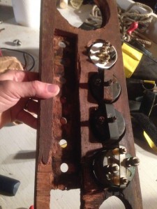
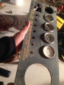
The next thing to keep in mind is the material of the panel: Never, under any circumstances, try to make it out of anything thicker than 1/4-inch. Switches, gauges, lights, etc. are all built for thin panels, and if you have something thicker you’ll be in for a lot of frustration. See my old panel for examples of futile and unnecessary adventures with a chisel…and see how trashed my old panel was. I just couldn’t put it back looking like that:


I have lately built all my instrument panels out of black, 1/4-inch Starboard. It’s easy to cut and drill, I think it looks good, and it’s got a matte texture that hides dirt and fingerprints.
As to engine instruments and senders, they’re just as confusing as they’ve always been. I’ve learned all about these things, and I still ran into trouble. Check out this email from VDO, a quality international gauge manufacturer who I’d bought three new gauges from. I’d spent hours on their website and just could not find what I needed:
Good Morning Mr. Beek,
Thank you for your inquiry.
This instrument is designed to work with the OEM sender that’s also a 220F Temp gauge. VDO does not manufacture a corresponding 220F temp sender. If you require a replacement, parts that may work can be found at;
Standard Ignition: TS-6 1/2′-14 thread
KEM Manufacturing” TW-3 12′-14 thread and TW-106 M114X1.25 thread
Autozone(Duralast): TU201, 3/8′-18 thread
Please let us know if we can further assist you.
VDO Sales Team
Kudos to them for at least telling me who I could buy the right bit from. As I said in Gauge of Confusion, the right sender for the gauge must cover the same range as the gauge, vary its resistance in the right range for the gauge, and be the right size to fit an existing hole in your engine. Drilling a new hole would take a leap of faith and risks a mistake that you’d be too embarrassed to share with others.
Looking at the right side of my instrument panel, we’ve got my good old mechanical tachometer, which has worked for nearly 50 years, so why change it? Next to that we’ve got the engine gauges for water temperature and oil pressure. Below those two gauges is the idiot light/buzzer for water temp and oil pressure. If that alarm goes off, I quickly check the gauges to see whether it’s high water temperature or a drop in oil pressure that has caused the alarm. I think it’s important to have both the idiot lights and the gauges: the gauges for precise readings and data over time; the idiot lights to actually alert you, unless you happen to be looking at the gauge when something goes wrong.
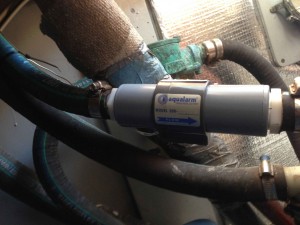
Under the tachometer is a second idiot light/buzzer. This one is for the new Aqualarm raw water flow sensor I installed:

After many years of fretting about my engine, it occurred to me that this flow sensor, attached to an alarm, could be key. You could have a complete raw water flow failure (failed pump, broken hose, blocked intake) and it would take several minutes for your engine to heat up enough to trigger the water temp idiot light. In the mean time you’re frying an impeller, melting your exhaust hose, and maybe damaging the engine itself. I wired it to a second idiot light/buzzer because it was a bit complicated and fiddly to have three different devices connected to the same light/buzzer and keep them straight. My flow sensor is just before the exhaust injection elbow, so it would tell me if anything had gone wrong in the entire raw water circuit.
Along the bottom of my panel are seven switches and fuses, which aren’t labled yet, but they are: Bilge blower, instrument lights, compass light, spare, windshield washer (yes, call me crazy, but when the salt gets caked on this will be a Godsend), port wiper, and starboard wiper.
On the left side of my panel I’ve got an Aqualarm Bilge Monitor, which I really like. Next to that is the old engine hour meter, which has the recorded hours on it, so I wasn’t about to change it. And next to that is the transmission pressure gauge, which always says the same thing no matter what, but I guess it would tell me if I lost my transmission fluid.
The big red thing at the lower left is a switch that silences the alarms, but the red thing would have to be sticking up like a sore thumb with the alarms turned off, so I won’t be able to forget. This way, when I’m starting the engine in the early morn I don’t have to wake everyone up with the alarms, as they will go off for 10-15 seconds until the flow switch gets triggered and the oil pressure comes up.
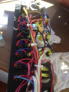
As to the wiring on the back of the panel, it looks like a rat’s nest, but it’s pretty simple:

Each gauge has three connections on the back, labeled +, GND, and Sender. The GND just goes to ship’s negative. The + should connect to the accessory tab on your ignition key, along with the regulator. Sender connects directly to the appropriate sender on your engine. Since your engine is grounded (negative in most cases) the sender makes or breaks, or varies the resistance of, this second negative connection to the gauge.
Each gauge also has a light, which needs positive and negative, so now we’ve got five wires connected to the back of each gauge. Many things on the backs of instrument panels can be daisy-chained together: Ship’s negative can hop from one negative connection on the back of a gauge, then the negative connection to the light on the gauge, and on to the next gauge. Same with positive from the key switch, which can go to all the gauges, and to the positive sides of the idiot lights. It’s okay to crimp up to three wires into the same ring or slip-on terminal.
You need circuit protection for your panel, so a fuse in line with the key switch is simple.
My bilge monitor is largely separate from the other stuff on the panel, and my row of seven switches has a separate feed and it’s own fuse.
The only problem with all this brand new teak and varnish is it makes the rest of the boat look like crap:
The steering wheel project work is great i like instrument panels Starboard. It’s easy to cut and drill this is amazing and looks good, and it’s got a matte texture that hides dirt and fingerprints Such a great detailed description of the whole process. it was very helpful. Thanks.